
Fiber optic loss testing is how you find out whether a fiber link was installed well. It measures how much light is lost between one end of a strand and the other, and compares that number to what the link should lose based on its length, connectors and splices. If you are paying for a new fiber backbone, the test report is the proof that you got what you paid for. This guide explains what the test does, how to read the results, and what to look for before you sign off.
What Fiber Optic Loss Testing Measures
Light weakens as it travels through glass and crosses each connection. That weakening is called loss, or attenuation, and it is measured in decibels (dB). Every part of a link adds some: the fiber itself, each mated connector pair and each splice. Too much total loss and the optics at each end may not link up, or may link with errors.
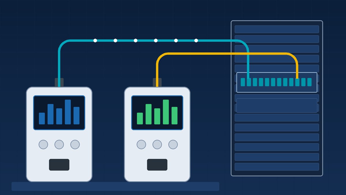
The test is simple in concept. A light source sends a stable signal into one end of the strand. A power meter at the other end measures how much arrives. The difference, compared to a reference reading taken before the test, is the loss of the link. This is called an insertion loss test, and it is done with a light source and power meter or an optical loss test set that combines the two.
The TIA-568.3-E standard describes this attenuation test, along with length and polarity checks, as the basic level of field testing and the default unless a project specifies otherwise. Industry references such as the Fiber Optic Association treat insertion loss as the test that qualifies a link.
How the Test Is Done
Inspect and clean first
Dirt on a connector end face is one of the most common causes of high loss. TIA-568.3-E calls for end faces to be inspected before each mating. A technician should look at every connector with a fiber inspection scope, clean it if needed and look again before plugging in. Never look into a fiber end or an active port with the naked eye.
Set the reference
Before measuring the link, the tester connects the source and meter with test reference cords and records a starting power level, often called “setting the zero.” How this is done affects every number on the report. TIA-568.3-E names the one-cord reference as the preferred method for testing links. With a one-cord reference, the loss of the connectors at both ends of the link is included in the result, which is what you want when you are judging the installed cabling. The method used should be written on the report.
Use the right wavelengths
Multimode fiber is tested at 850 nm and 1300 nm. Single-mode fiber is tested at 1310 nm and 1550 nm. TIA-568.3-E requires backbone fiber to be tested at both wavelengths for its type, in at least one direction. Testing at two wavelengths catches problems one wavelength can miss. For example, single-mode fiber is more sensitive to tight bends at 1550 nm, so a bend that looks fine at 1310 nm may show up clearly at 1550 nm.
Use the right launch for multimode
For multimode testing, the way light is launched into the fiber changes the result. The test method TIA-568.3-E references for multimode, ANSI/TIA-526-14, calls for an encircled flux launch at the output of the launch cord. In plain terms, the tester should use equipment and cords set up for consistent multimode results. Ask your installer how they meet it.
Check polarity and length
Polarity confirms that the transmit fiber at one end reaches the receive port at the other. It can be checked during the loss test, from labels, or with a visual fault locator that shines visible red light down the strand. Length can come from the footage markings on the cable jacket or from the as-built drawings, and should be recorded with the results.
How to Calculate a Loss Budget
A loss budget is the most a link should lose. You add up an allowance for each part of the link and compare the test result to the total. TIA-568.3 gives default maximum values that are widely used for this:
| Component | TIA-568.3 maximum allowance |
|---|---|
| Multimode fiber at 850 nm | 3.5 dB per km |
| Multimode fiber at 1300 nm | 1.5 dB per km |
| Single-mode fiber, inside plant | 1.0 dB per km |
| Single-mode fiber, outside plant | 0.5 dB per km |
| Mated connector pair | 0.75 dB |
| Splice | 0.3 dB |
A worked example
Take a 150-meter multimode backbone between a data room and a closet. Each end has a patch panel with fusion-spliced pigtails, so the link has two mated connector pairs (one at each panel) and two splices. Tested with a one-cord reference, both end connectors count.
- Fiber at 850 nm: 0.15 km x 3.5 dB/km = 0.53 dB
- Connectors: 2 x 0.75 dB = 1.50 dB
- Splices: 2 x 0.3 dB = 0.60 dB
- Loss budget at 850 nm: about 2.6 dB
At 1300 nm the fiber term drops to about 0.23 dB, so the budget is about 2.3 dB. A well-installed link of this kind usually tests well under these numbers, because good connectors and splices lose less than the maximum allowance. The budget is a ceiling, not a target.
One more check matters: the optics. Each Ethernet speed and optic type has its own maximum channel loss, and faster multimode optics generally allow less. Before you plan an upgrade, compare the tested loss to the specification for the optic you intend to use. Our guide to SFP modules and fiber uplinks explains how optics are matched to fiber.
How to Read a Fiber Test Report
TIA-568.3-E recommends that a loss test record identify the following. If any of it is missing, ask for it.
- Date of the test and the technician who ran it
- The test instrument and its calibration
- The fiber and strand identifiers, matching the labels on the panel
- The test procedure and the reference method used
- The launch condition (for multimode)
- Loss at each wavelength, in each direction tested
Also look for the loss budget or pass limit next to each result, so you can see the margin, plus polarity and length for each strand.
Red flags on a report
- Negative loss readings. A passive link cannot add light. A reading below zero usually means the reference was set incorrectly or a cord changed during testing.
- Only one wavelength on backbone fiber. The standard calls for both.
- Missing strands. Every terminated strand should appear, including spares.
- Identical numbers on every strand. Real results vary a little from strand to strand.
- No reference method listed. Without it, the numbers cannot be compared to a budget.
- Labels that do not match the panel. The report should map directly to what is in the rack. See how to label network cables for a simple scheme.
What Causes High Loss on a Fiber Test
When a strand fails or has little margin, the usual causes are:
- Dirty or damaged connectors. Cleaning and re-testing fixes many failures.
- Tight bends. Slack coiled too tightly in a panel, a cable pinched by a tie wrap or a sharp turn in a pathway. These often show more loss at the longer wavelength.
- A poor splice. A bad cleave or contamination at the splice point. The fix is to re-splice.
- Mismatched fiber. A multimode pigtail spliced to a different grade, or single-mode mixed with multimode.
- Cable damage. A crush or kink during the pull, or later work by another trade.
A visual fault locator can help find breaks and sharp bends near the ends of a link, where the red light leaks out of the jacket.
Testing Copper Is a Different Job
Fiber loss testing applies to fiber only. Copper cabling such as Cat6 and Cat6A is checked with a cable certifier against TIA category limits. If your project includes both, you should get both sets of results. Our guide to testing Ethernet cabling covers the copper side.
FAQ: Fiber Optic Loss Testing
Is fiber optic loss testing required?
For a professional installation, it should be. TIA-568.3-E treats the insertion loss test, with length and polarity checks, as the default field test. Many building owners and IT teams require test results for every strand before they accept the work.
What is a good loss reading for fiber?
There is no single number. A good reading is one that falls under the loss budget for that link’s length, connectors and splices, with some margin to spare, and under the limit for the optics you plan to run. A short in-building link with two panels should usually measure well under its budget.
Can existing fiber be tested?
Yes. If your building has fiber with no records, or you are not sure which strands are good, a loss test on each strand tells you what is usable. That is often the first step before adding switches or upgrading to faster optics.
Why test at two wavelengths?
Different problems show up at different wavelengths. Bend-related loss in single-mode fiber is more visible at 1550 nm, and testing both wavelengths gives a fuller picture of the link. TIA-568.3-E requires both for backbone fiber.
Does a pre-terminated cable need testing after installation?
Yes. The factory report shows the assembly was good when it left the plant. A test after installation confirms it survived the pull and that every connection is clean. See fusion splicing vs pre-terminated fiber for more on the two methods.
Get Fiber Installed and Tested by Chain
Chain installs, fusion splices and loss tests fiber for businesses across the Mid-Atlantic. We test every fiber strand after installation, and our copper cabling is certification tested, so you get results for the whole system, labeled to match the panels. We are licensed and insured and also set up the switches and WiFi the fiber feeds. See our fiber optic services, structured cabling and networking and WiFi pages, or check whether you are in our service area. To test existing fiber or plan a new link, contact us.